 Arduino(アルドゥイーノ)演習参照アドレス
Arduino(アルドゥイーノ)演習は下記のアドレスを参照します。
https://www.arduino.cc/en/Tutorial/HomePage
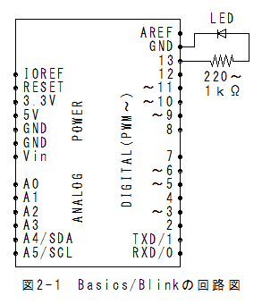
Basics/Blinkの回路図Basics/Blinkの回路図を以下に示します。
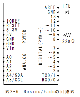
LEDの電流制限用として220~1kΩの抵抗を直列に挿入します。
 Basics/Blinkのスケッチ
(1)メニューの「ファイル」_「スケッチの例」_「Basics」_「Blink」で以下のスケッチが設定されます。
/*
  Blink
  Turns on an LED on for one second, then off for one second, repeatedly.

  Most Arduinos have an on-board LED you can control. On the Uno and
  Leonardo, it is attached to digital pin 13. If you're unsure what
  pin the on-board LED is connected to on your Arduino model, check
  the documentation at http://www.arduino.cc

  This example code is in the public domain.

  modified 8 May 2014
  by Scott Fitzgerald
 */


// the setup function runs once when you press reset or power the board
void setup() {
  // initialize digital pin 13 as an output.
  pinMode(13, OUTPUT);
}

// the loop function runs over and over again forever
void loop() {
  digitalWrite(13, HIGH);   // turn the LED on (HIGH is the voltage level)
  delay(1000);              // wait for a second
  digitalWrite(13, LOW);    // turn the LED off by making the voltage LOW
  delay(1000);	// wait for a second
}
Basics/Blinkの実行(1)メニューの「スケッチ」_「マイコンボードに書き込む」で書込みされ、実行されます。
(2)LEDが1秒毎に点滅します。
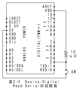
Basics/Digital Read Serialの回路図Basics/Digital Read Serialの回路図を以下に示します。
 Basics/Digital Read Serialのスケッチ
(1)メニューの「ファイル」_「スケッチの例」_「Basics」_「Digital Read Serial」でスケッチが設定されます。
(2)送信間隔を長くするためにdelay(1); をdelay(1000); に変更します。**注(1)
/*
  DigitalReadSerial
 Reads a digital input on pin 2, prints the result to the serial monitor

 This example code is in the public domain.
 */

// digital pin 2 has a pushbutton attached to it. Give it a name:
int pushButton = 2;

// the setup routine runs once when you press reset:
void setup() {
  // initialize serial communication at 9600 bits per second:
  Serial.begin(9600);
  // make the pushbutton's pin an input:
  pinMode(pushButton, INPUT);
}

// the loop routine runs over and over again forever:
void loop() {
  // read the input pin:
  int buttonState = digitalRead(pushButton);
  // print out the state of the button:
  Serial.println(buttonState);
  delay(1000);	//**注(1) 1→1000に変更
}
Basics/Digital Read Serialの実行(1)メニューの「スケッチ」_「マイコンボードに書き込む」で書込みされ、実行されます。
(2)メニューの「ツール」_「シリアルモニタ」を選択するとシリアルモニタが表示されます。
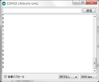
(3)スイッチを押すと1が表示され、離すと0が表示されます。
(4)実行結果を以下に示します。
 Basics/Analog Read Serialの回路図
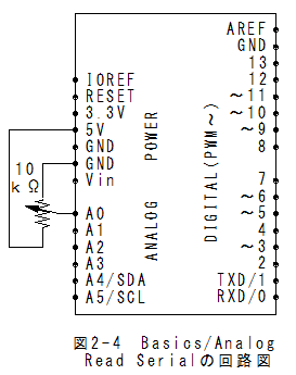
Basics/Analog Read Serialの回路図を以下に示します。
 Basics/Analog Read Serialの回路図のスケッチ
(1)メニューの「ファイル」_「スケッチの例」_「Basics」_「Basics/Analog Read Serial」でスケッチが設定されます。
(2)送信間隔を長くするためにdelay(1); をdelay(1000); に変更します。**注(1)
/*
  AnalogReadSerial
  Reads an analog input on pin 0, prints the result to the serial monitor.
  Attach the center pin of a potentiometer to pin A0, and the outside pins to +5V and ground.

 This example code is in the public domain.
 */

// the setup routine runs once when you press reset:
void setup() {
  // initialize serial communication at 9600 bits per second:
  Serial.begin(9600);
}

// the loop routine runs over and over again forever:
void loop() {
  // read the input on analog pin 0:
  int sensorValue = analogRead(A0);
  // print out the value you read:
  Serial.println(sensorValue);
  delay(1000);	//**注(1) 1→1000に変更
}
Analog Read Serialの実行(1)メニューの「スケッチ」_「マイコンボードに書き込む」で書込みされ、実行されます。
(2)メニューの「ツール」_「シリアルモニタ」を選択するとシリアルモニタが表示されます。
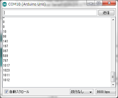
(3)ボリュウムを回すと値が0から1023の範囲で変化することが確認できます。
(4)実行結果を以下に示します。
 Basics/Fadeの回路図
Basics/Fadeの回路図を以下に示します。
 Basics/Fadeの回路図のスケッチ
(1)メニューの「ファイル」_「スケッチの例」_「Basics」_「Fade」でスケッチが設定されます。
/*
 Fade

 This example shows how to fade an LED on pin 9
 using the analogWrite() function.

 This example code is in the public domain.
 */

int led = 9;           // the pin that the LED is attached to
int brightness = 0;    // how bright the LED is
int fadeAmount = 5;    // how many points to fade the LED by

// the setup routine runs once when you press reset:
void setup() {
  // declare pin 9 to be an output:
  pinMode(led, OUTPUT);
}

// the loop routine runs over and over again forever:
void loop() {
  // set the brightness of pin 9:
  analogWrite(led, brightness);

  // change the brightness for next time through the loop:
  brightness = brightness + fadeAmount;

  // reverse the direction of the fading at the ends of the fade:
  if (brightness == 0 || brightness == 255) {
    fadeAmount = -fadeAmount ;
  }
  // wait for 30 milliseconds to see the dimming effect
  delay(30);
}
Basics/Fadeの実行(1)メニューの「スケッチ」_「マイコンボードに書き込む」で書込みされ、実行されます。
(2)LEDが連続的に明るくなったり、暗くなったりします。
Basics/Analog Read Voltageの回路図Basics/Analog Read Voltageの回路図はBasics/Analog Read Serialの回路図と同じとなります。
Basics/Analog Read Voltageのスケッチ(1)メニューの「ファイル」_「スケッチの例」_「Basics」_「Analog Read Voltage」でスケッチが設定されます。
(2)送信間隔を長くするためにdelay(1000); を追加します。**注(1)
/*
  ReadAnalogVoltage
  Reads an analog input on pin 0, converts it to voltage, and prints the result to the serial monitor.
  Attach the center pin of a potentiometer to pin A0, and the outside pins to +5V and ground.

 This example code is in the public domain.
 */

// the setup routine runs once when you press reset:
void setup() {
  // initialize serial communication at 9600 bits per second:
  Serial.begin(9600);
}

// the loop routine runs over and over again forever:
void loop() {
  // read the input on analog pin 0:
  int sensorValue = analogRead(A0);
  // Convert the analog reading (which goes from 0 - 1023) to a voltage (0 - 5V):
  float voltage = sensorValue * (5.0 / 1023.0);
  // print out the value you read:
  Serial.println(voltage);
  delay(1000);	//**注(1) delay(1000); を追加
}
Analog Read Voltageの実行(1)メニューの「スケッチ」_「マイコンボードに書き込む」で書込みされ、実行されます。
(2)メニューの「ツール」_「シリアルモニタ」を選択するとシリアルモニタが表示されます。
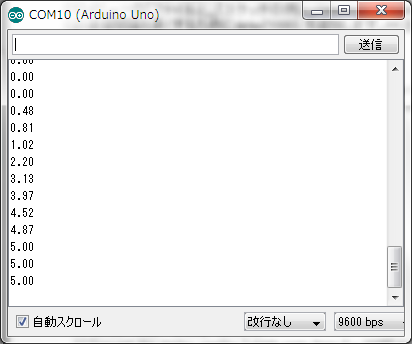
(3)ボリュウムを回すと値が0.00から5.00の範囲で変化することが確認できます。
(4)実行結果を以下に示します。
 Arduino(アルドゥイーノ)演習(Basics編)まとめ
(1)BlinkではLEDのON/OFF制御方法が理解できます。
(2)Digital Read Serialでは、デジタル入力とUSBデータ送信方法が理解できます。
(3)Analog Read Serialでは、アナログ入力とUSBデータ送信方法が理解できます。
(4)Fadeでは、PWMによるアナログ出力方法が理解できます。
(5)Analog Read Voltageでは、アナログ入力の電圧変換係数は5.0/1023.0であることが理解できます。
(6)Arduino IDEでは、シリアルモニタ機能があり、USBデータ送信とUSBデータ受信内容の確認が可能です。
(7)シリアルモニタ機能が無い場合は、Windows用のシリアルモニタ機能アプリを製作する必要があります。
(8)Windows用のシリアルモニタ機能アプリの製作は結構難解なのですが、Windows側で受信データの変換処理が可能となります。
*Arduino(アルドゥイーノ)演習(Basics編)の理解はさほど難しくありませんでした。
 3章:Windows用シリアルモニタ_プログラムに行く。