Arduino-UNOとAE-USBPIC44基板のシリアル通信について検討してみました。
 Arduino(アルドゥイーノ)演習参照アドレス
Arduino(アルドゥイーノ)演習は下記のアドレスを参照します。
https://www.arduino.cc/en/Tutorial/HomePage
Software Serial Libraryを使用した概略回路図Software Serial Libraryを使用した概略回路図は以下となります。
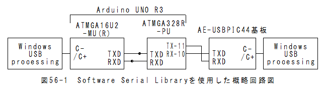
*Arduino-UNOはUSB通信とUSART通信が連動しており独立に制御できません。
*USB通信とUSART通信を独立に制御したい場合、Software Serial Libraryを使用します。
*これに対して、AE-USBPIC44基板はUSB通信とUSART通信が独立して動作します。
*USART通信がソフト処理となるため、ボーレート設定値が制限されます。
*動作ボーレートを確認したところ9600bpsでは正常に動作し、14400bpsでは動作しませんでした。
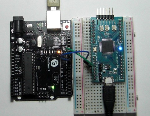
Software Serial Libraryを使用した回路外観Software Serial Libraryを使用した回路外観を以下に示します。
 Arduino-UNOのスケッチ
(1)メニューの「ファイル」_「スケッチの例」_「SoftwareSerial」_「SoftwareSerialExample」でスケッチが設定されます。
(2)Serial.begin(57600);を9600bpsに修正します。
(3)mySerial.begin(4800);を9600bpsに修正します。
スケッチは以下となります。
/* Software serial multple serial test Receives from the hardware serial, sends to software serial. Receives from software serial, sends to hardware serial. The circuit: * RX is digital pin 10 (connect to TX of other device) * TX is digital pin 11 (connect to RX of other device) Note: Not all pins on the Mega and Mega 2560 support change interrupts, so only the following can be used for RX: 10, 11, 12, 13, 50, 51, 52, 53, 62, 63, 64, 65, 66, 67, 68, 69 Not all pins on the Leonardo support change interrupts, so only the following can be used for RX: 8, 9, 10, 11, 14 (MISO), 15 (SCK), 16 (MOSI). created back in the mists of time modified 25 May 2012 by Tom Igoe based on Mikal Hart's example This example code is in the public domain. */ #includeSoftwareSerial mySerial(10, 11); // RX, TX void setup() { // Open serial communications and wait for port to open: Serial.begin(9600); while (!Serial) { ; // wait for serial port to connect. Needed for Leonardo only } Serial.println("Goodnight moon!"); // set the data rate for the SoftwareSerial port mySerial.begin(9600); mySerial.println("Hello, world?"); } void loop() // run over and over { if (mySerial.available()) Serial.write(mySerial.read()); if (Serial.available()) mySerial.write(Serial.read()); }
AE-USBPIC44基板のソースプログラムMPLAB_X_IDE_v2.25とPIC18F4553マイコンの復習
26章:AE-USBPIC44基板使用シリアル-USB変換モジュール
(3)シリアル-USB変換モジュールソースプログラム(送信側)
と同一となります。
 [../f41/26-1.zip]をダウンロードする。
解凍するとMy-CDC-Basic.Xフォルダーがあります。
ボーレートの変更ボーレートの変更はありません。
MAIN_RETURN main(void)
{
    ADCON1  =	0b00001111;
    TRISA   =	0b00000000;
    TRISB   =	0b00000000;
    TRISC   =	0b00110000;         //D-,D+
    TRISD   =	0b00000000;
    TRISE   =   0b11000011;         //SW1,2=INPUT LED=OUTPUT
    LATA    =	0b00000000;
    LATB    =	0b00000000;
    LATC    =	0b00000000;
    LATD    =	0b00000000;
    LATE    =	0b00000000;

    SYSTEM_Initialize(SYSTEM_STATE_USB_START);
    USBDeviceInit();
    USBDeviceAttach();

    UART_Init(9600);
    RCIF = 0; //reset RX pin flag
    RCIP = 1; //high priority
    RCIE = 1; //Enable RX interrupt
    PEIE = 1; //Enable pheripheral interrupt (serial port is a pheripheral)
    INTCONbits.GIE = 1;
    int i;
    uint8_t Buffer[256];
    while(1)
    {
        LED=0;
        if(gN>=1)
        {
            if( USBUSARTIsTxTrfReady() == true)
            {
                uint8_t iN=gN;
                gN=0;
                LED=1;
                for(i=0;i<iN;i++)
                {
                    Buffer[i]=UARTreadBuffer[i];
                }
                putUSBUSART(Buffer,iN);//USB送信
            }
        }
        SYSTEM_Tasks();
        #if defined(USB_POLLING)
            USBDeviceTasks();
        #endif
        if( USBGetDeviceState() < CONFIGURED_STATE ){continue;}
        if( USBIsDeviceSuspended()== true ) {continue;}
        MyCDCBasicTasks();
    }
}
Windows送信側のスケッチprocessingを使用します。送信側は以下のスケッチとなります。
//USB-シリアル変換テスト用(送信側)
import processing.serial.*;
Serial myPort;

void setup()
{
   println(Serial.list());
   myPort = new Serial(this, Serial.list()[4],9600);
   myPort.bufferUntil('\n');
}

void draw()
{
  char i;
  for(i=0x61;i<=0x7A;i++)
  {
    myPort.write(i);
    //delay(1);
  }
  myPort.write('\n');
  delay(100);
}

void serialEvent(Serial myPort)
{
  String inString = myPort.readStringUntil('\n');
  if (inString != null)
  {
    print(inString);
  }
}
* myPort = new Serial(this, Serial.list()[4],115200);のリストナンバーは環境に応じて変更します。Windows受信側のスケッチprocessingを使用します。受信側は以下のスケッチとなります。
//USB-シリアル変換テスト用(受信側)
import processing.serial.*;
Serial myPort;

void setup()
{
   println(Serial.list());
   myPort = new Serial(this, Serial.list()[5],9600);
   myPort.bufferUntil('\n');
}

void draw()
{
}

void serialEvent(Serial myPort)
{
  String inString = myPort.readStringUntil('\n');
  if (inString != null)
  {
    print(inString);
  }
}
* myPort = new Serial(this, Serial.list()[4],115200);のリストナンバーは環境に応じて変更します。使用方法と評価結果(1)Arduino-UNOとAE-USBPIC44基板にそれぞれプログラムを書込みます。
(2)processingのウインドウを2個開き、Windows送信側のスケッチとWindows受信側のスケッチをペーストします。
(3)myPort = new Serial(this, Serial.list()[4],9600);のリストナンバーは環境に応じて変更します。
(4)Windows送信側のスケッチとWindows受信側のスケッチをそれぞれRunします。
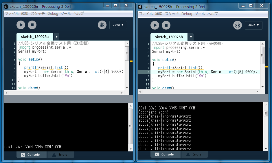
(5)以下のような画面となります。
*myPort = new Serial(this, Serial.list()[4],9600);のリストナンバーを入れ替えると受信側と送信側を入れ替えると以下のようになります。
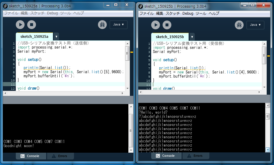
*Hello, world?が正しく受信できておりません。
*abcdefghijklmnopqrstuvwxyzはどちらの送信方向についてもエラー率はゼロでした!!
*ボーレート14400bpsでは動作しませんでした。
*abcdefghijklmnopqrstuvwxyz送信では、USB側からとUART側からの同時受信を避けるようにしました。
*USB側からとUART側からの同時受信があるとエラー率が上昇する可能性があります。
Arduino-UNOとAE-USBPIC44基板のシリアル通信(2)まとめ(1)Arduino-UNOはUSB通信とUSART通信が連動しており独立に制御できません。
(2)USB通信とUSART通信を独立に制御したい場合、Software Serial Libraryを使用します。
(3)これに対して、AE-USBPIC44基板はUSB通信とUSART通信が独立して動作します。
(4)USART通信がソフト処理となるため、ボーレート設定値が制限されます。
(5)動作ボーレートを確認したところ9600bpsでは正常に動作し、14400bpsでは動作しませんでした。
(6)abcdefghijklmnopqrstuvwxyz送信では、USB側からとUART側からの同時受信を避けるようにしました。
(7)USB側からとUART側からの同時受信があるとエラー率が上昇する可能性があります。
 57章:AVRマイコンATMEGA328P-PUへのブートローダの書込み方法に行く。