Processingの3D機能を利用して3D機械製図への応用を検討してみたいと思います。
 パイプクランプの寸法図
パイプクランプは加工品となります。
パイプクランプの寸法図を以下に示します。
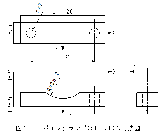
*図27-1からパイプクランプの基本寸法はL1、L1、L2、L3、L4、L5、R、rの7個のパラメータで形状が決まります。 *パラメータは全てfloat型でmm単位で入力とします。
3Dサンプル(sketch_3D_STD_01)パイプクランプスケッチ3Dサンプル(sketch_3D_STD_01)パイプクランプスケッチは以下となります。
//sketch_3D_STD_01 パイプクランプ
void setup()
{
  size(400, 400, P3D);
}

void draw()
{
  background(255, 255, 255);
  lights();
  ortho(-width/2, width/2, -height/2, height/2); // Same as ortho()
  translate(width / 2, height / 2);
  rotateY(map(mouseX, 0, width, -PI/1, PI/1));
  rotateX(map(mouseY, 0, height, PI/1, -PI/1));
  //noStroke();
  strokeWeight(0.1);

  fill(255, 255, 255);
  scale(2,2,2);

  STD_01(120,30,20,30,90,38.2,7);//STD_01)パイプクランプ
}
//STD_01)パイプクランプ
void STD_01(float L1,float L2,float L3,float L4,float L5,float R,float r)
{
  int An=8;
  int Pn=An+6;//ポイント数
  float[] X=new float[Pn];
  float[] Z=new float[Pn];
  int i;
  float dA=2*acos(L4/R)/An;;
  //float AA=dA*4;
  for(i=0;i<= An;i++)
  {
    float angle = (i-An/2)*dA;
    X[i]=R*sin(angle);Z[i]=R*cos(angle);
  }
  X[An+1]=L1/2;Z[An+1]=L4;
  X[An+2]=L1/2;Z[An+2]=L4+L3;
  X[An+3]=-L1/2;Z[An+3]=L4+L3;
  X[An+4]=-L1/2;Z[An+4]=L4;
  X[An+5]=X[0];Z[An+5]=Z[0];
  Y_Side(An+1,X,Z,L2);//側面


  int Pn2=5;//ポイント数
  float[] X2=new float[Pn2];
  float[] Y2=new float[Pn2];
  float[] Z2=new float[Pn2];

  int Pn3=17;//ポイント数
  float[] X3=new float[Pn3];
  float[] Y3=new float[Pn3];
  for(i=0;i<Pn3;i++)
  {
    float angle = i*TWO_PI/(Pn3-1);
    X3[i]=r*cos(angle)+L5/2;Y3[i]=r*sin(angle);
  }

  int Pn4=17;//ポイント数
  float[] X4=new float[Pn4];
  float[] Y4=new float[Pn4];
  for(i=0;i<Pn4;i++)
  {
    float angle = i*TWO_PI/(Pn4-1);
    X4[i]=r*cos(angle)-L5/2;Y4[i]=r*sin(angle);
  }


  X2[0]=X[An];Y2[0]=-L2/2;
  X2[1]=L1/2;Y2[1]=-L2/2;
  X2[2]=L1/2;Y2[2]=L2/2;
  X2[3]=X[An];Y2[3]=L2/2;
  X2[4]=X[An];Y2[4]=-L2/2;
  beginShape();
  Z_Polyon_PZ(Pn2,X2,Y2,L4);//多角形
  beginContour();
  Z_Polyon_MZ(Pn3-1,X3,Y3,L4);//多角形
  endContour();
  endShape(CLOSE);

  X2[0]=-X[An];Y2[0]=-L2/2;
  X2[1]=-X[An];Y2[1]=L2/2;
  X2[2]=-L1/2;Y2[2]=L2/2;
  X2[3]=-L1/2;Y2[3]=-L2/2;
  X2[4]=-X[An];Y2[4]=-L2/2;
  beginShape();
  Z_Polyon_PZ(Pn2,X2,Y2,L4);//多角形
  beginContour();
  Z_Polyon_MZ(Pn4-1,X4,Y4,L4);//多角形
  endContour();
  endShape(CLOSE);

  X2[0]=L1/2;Y2[0]=L2/2;
  X2[1]=-L1/2;Y2[1]=L2/2;
  X2[2]=-L1/2;Y2[2]=-L2/2;
  X2[3]=L1/2;Y2[3]=-L2/2;
  X2[4]=L1/2;Y2[4]=L2/2;

  beginShape();
  Z_Polyon_PZ(Pn2,X2,Y2,L3+L4);//多角形
  beginContour();
  Z_Polyon_MZ(Pn3-1,X3,Y3,L3+L4);//多角形
  endContour();
  beginContour();
  Z_Polyon_MZ(Pn4-1,X4,Y4,L3+L4);//多角形
  endContour();
  endShape(CLOSE);

  pushMatrix();
  translate(0,0,L4+L3/2);
  Z_Side(Pn3,X3,Y3,L3);//側面
  Z_Side(Pn4,X4,Y4,L3);//側面
  popMatrix();

  Y2[0]=-L2/2;Z2[0]=L4;
  Y2[1]=L2/2;Z2[1]=L4;
  Y2[2]=L2/2;Z2[2]=L4+L3;
  Y2[3]=-L2/2;Z2[3]=L4+L3;
  Y2[4]=-L2/2;Z2[4]=L4;
  beginShape();
  X_Polyon_PX(Pn2,L1/2,Y2,Z2);//多角形
  endShape(CLOSE);
  beginShape();
  X_Polyon_PX(Pn2,-L1/2,Y2,Z2);//多角形
  endShape(CLOSE);

  beginShape();
  Y_Polyon_PY(Pn,X,-L2/2,Z);//多角形
  endShape(CLOSE);
  beginShape();
  Y_Polyon_PY(Pn,X,L2/2,Z);//多角形
  endShape(CLOSE);
}


void Z_Side(int Pn,float X[],float Y[],float L)//側面
{
  int i;
  beginShape(QUAD_STRIP);
  for (i = 0; i < Pn; i++)
  {
    vertex(X[i],Y[i], -L/2);
    vertex(X[i],Y[i], L/2);
  }
  endShape(CLOSE);
}

void Y_Side(int Pn,float X[],float Z[],float L)//Y軸 側面
{
  int i;
  beginShape(QUAD_STRIP);
  for (i = 0; i < Pn; i++)
  {
    vertex(X[i],-L/2,Z[i]);
    vertex(X[i],L/2,Z[i]);
  }
  endShape(CLOSE);
}

void Z_Polyon_P(int Pn,float X[],float Y[])//多角形反時計回り
{
  int i;
  for (i = 0; i < Pn; i++)
  {
    vertex(X[i],Y[i]);
  }
}

void Z_Polyon_PZ(int Pn,float X[],float Y[],float Z)//多角形反時計回り
{
  int i;
  for (i = 0; i < Pn; i++)
  {
    vertex(X[i],Y[i],Z);
  }
}

void Y_Polyon_P(int Pn,float X[],float Z[])//Y軸 多角形反時計回り
{
  int i;
  for (i = 0; i < Pn; i++)
  {
    vertex(X[i],0,Z[i]);
  }
}

void Y_Polyon_PY(int Pn,float X[],float Y,float Z[])//Y軸 多角形反時計回り
{
  int i;
  for (i = 0; i < Pn; i++)
  {
    vertex(X[i],Y,Z[i]);
  }
}

void X_Polyon_PX(int Pn,float X,float Y[],float Z[])//X軸 多角形反時計回り
{
  int i;
  for (i = 0; i < Pn; i++)
  {
    vertex(X,Y[i],Z[i]);
  }
}

void Z_Polyon_M(int Pn,float X[],float Y[])//多角形時計回り
{
  int i;
  for (i = Pn-1; i >= 0; i--)
  {
    vertex(X[i],Y[i]);
  }
}

void Z_Polyon_MZ(int Pn,float X[],float Y[],float Z)//多角形時計回り
{
  int i;
  for (i = Pn-1; i >= 0; i--)
  {
    vertex(X[i],Y[i],Z);
  }
}
3Dサンプル(sketch_3D_STD_01)パイプクランプテキストファイル3Dサンプル(sketch_3D_STD_01)パイプクランプテキストファイルは以下から参照できます。
 「3Dサンプル(sketch_3D_STD_01)パイプクランプファイル」にいく3Dサンプル(sketch_3D_STD_01)パイプクランプスケッチの実行
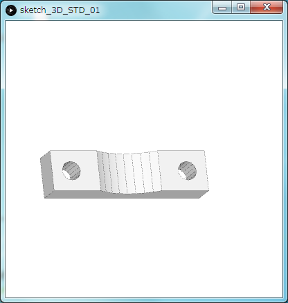
(1)3Dサンプル(sketch_3D_STD_01)パイプクランプを実行すると実行ウインドウに3D画像が表示されます。
(2)マウスを動かすと表示角度が変化します。
(3)表示画像例を以下に示します。
 3Dサンプル(sketch_3D_STD_01)パイプクランプまとめ
(1)表示は正投影のortho(-width/2, width/2, -height/2, height/2);としました。
(2)線有りのstrokeWeight(0.1);としました。
(3)STD_01(120,30,20,30,90,38.2,7);//STD_01)パイプクランプと指定すると指定寸法のパイプクランプが表示できます。
(4)これまでの検討で、ほとんどのパーツの作図が可能であることが可能であることが理解できました。
(5)穴開けはプログラム的な制限事項があり、やや面倒です。(面倒な場合は、省略することも可能と思います。)
(6)実際の作図では、多くのパーツの組合せとなります。
(7)パーツ数が増大した場合、応答性に問題が生じないか心配です。
(8)この辺で、作成したスケッチの整理をしてみたいと思います。