技適済み格安高性能Wi-FiモジュールESP8266をArduinoIDEを使ってIoT開発する為の環境準備を10分でやる方法
http://qiita.com/azusa9/items/264165005aefaa3e8d7d
**丁寧に解説されています
Arduino core for ESP8266 WiFi chip
https://github.com/esp8266/Arduino
Arduinoの環境にESP8266チップのサポートをもたらします。使い慣れたArduinoの機能とライブラリを使用してスケッチを書き、ESP8266マイクロコントローラ上で直接それらを実行することができます。
Installing with Boards Manager
Arduino1.6.4以降のボードは、マネージャを使用してサードパーティのプラットフォームパッケージのインストールが可能です。
(1)ArduinoのウェブサイトからのArduino1.6.5をインストールしてください。
(2)環境設定ウィンドウを開いてください。
(3)ボードマネージャの追加URLフィールドにhttp://arduino.esp8266.com/stable/package_esp8266com_index.jsonを入力します。
カンマで区切って、複数のURLを追加することができます。
(4)ツールからボードマネージャをオープンします。
ボードメニューのesp8266プラットフォームをインストールします。
(ツールからESP8266ボードを選択することを忘れないでください。)
*ここが供給元です。
(1)開発環境のダウンロード先アドレス:以下のアドレスからダウンロードできます。
https://www.arduino.cc/en/Main/Software
(1)"arduino.exe"をダブルクリックで起動します。
(2)メニュー「ファイル」_「環境設定」を選択します。
(3)Additional Boards Manager URLs:に以下の設定をします。
http://arduino.esp8266.com/stable/package_esp8266com_index.json

(4)メニュー「ツール」_「ボード」_「Boads Manager」を選択します。
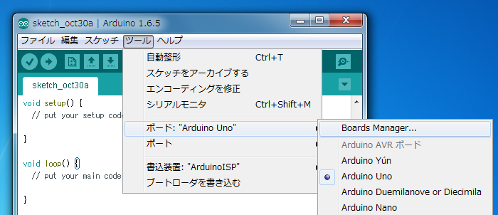
(5)「Boads Manager」のサーチ欄にespと入力すると検索できます。

(6)「Insutall」ボタンを押します。
(7)「Boads Manager」を閉じます。
(8)メニュー「ツール」_「ボード」_「Genric ESP8266 Module」を選択します。
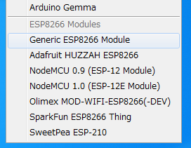
(9)メニュー「ファイル」_「スケッチの例」_「esp8266」_「Blink」を選択します。
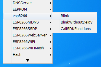
(10)以下のスケッチが設定されます。
/*
 ESP8266 Blink by Simon Peter
 Blink the blue LED on the ESP-01 module
 This example code is in the public domain

 The blue LED on the ESP-01 module is connected to GPIO1
 (which is also the TXD pin; so we cannot use Serial.print() at the same time)

 Note that this sketch uses BUILTIN_LED to find the pin with the internal LED
*/

void setup() {
  pinMode(BUILTIN_LED, OUTPUT);     // Initialize the BUILTIN_LED pin as an output
}

// the loop function runs over and over again forever
void loop() {
  digitalWrite(BUILTIN_LED, LOW);   // Turn the LED on (Note that LOW is the voltage level
                                    // but actually the LED is on; this is because
                                    // it is acive low on the ESP-01)
  delay(1000);                      // Wait for a second
  digitalWrite(BUILTIN_LED, HIGH);  // Turn the LED off by making the voltage HIGH
  delay(2000);                      // Wait for two seconds (to demonstrate the active low LED)
}
(11)USBシリアル変換モジュールをパソコンに接続し、デバイスマネージャーのポートで接続ポートを確認します。(COM14に接続しました。)
(12)ESP-WROOM-02のフラッシュ書き換え時のピン設定
*ENピン:(Chip Enable.)→High(10kΩプルアップ)
*GPIO-15ピン:(Type I/O MTDO;HSPI_CS; UART0_RTS)→LowHigh(10kΩプルダウン)
*GPIO-2ピン:(Type I/O UART Tx during flash programming)→High(10kΩプルアップ)
*GPIO-0ピン:(Type I/O SPI_CS2)→Low(10kΩプルダウン)(Lowでラッシュ書き換えモード)
*TXピン:USBシリアル変換モジュールのRX
*RXピン:USBシリアル変換モジュールのTX
*GNDピン:USBシリアル変換モジュールのGND
*最後にTXピン:LEDと1kΩ抵抗を直列に接続します。
(13)ESP-WROOM-02の電源を投入します。
(14)メニュー「ツール」_「ポート」_「COM14」を選択します。
(15)メニュー「スケッチ」_「マイコンボードに書込む」を選択します。
(16)書込みが完了して以下のようになります。
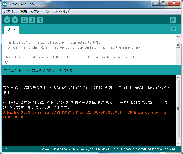
(17)GPIO-0ピン:(Type I/O SPI_CS2)→High(10kΩプルアップ)に戻します。
(18)ESP-WROOM-02の電源を再投入します。
(19)TXピンに接続したLEDが点滅します。
評価回路外観を以下に示します。(紫と白色の配線は10kΩ抵抗付きの配線を使用しました。)
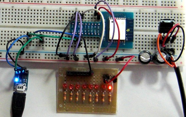
(1)ESP-WROOM-02とArduinoIDEでLED点滅は思いのほか簡単に動作しました。
(2)ESP-WROOM-02のプログラムがこれほど簡単にできるとは!!驚きです!!
(3)https://github.com/esp8266/Arduinoはすばらしい!!