(1)購入先:アマゾン
(2)名称:サインスマート UNO R3 ATmega328P 互換ボード + USBケーブル(Arduino UNO R3 Mega 2560 に対応)オリジナルバージョン
(3)価格:¥1850(配送無料)
サインスマート UNO R3 ATmega328P 互換ボードの外観を以下に示します。

(1)開発環境のダウンロード先アドレス:以下のアドレスからダウンロードできます。
https://www.arduino.cc/en/Main/Software
(2)ダウンロードファイル:以下のファイルをダウンロードしました。
ARDUINO 1.6.5 Windows Installer を選択
arduino-1.6.5-r2-windows.exeファイルがダウンロードできました。
(1)arduino-1.6.5-r2-windows.exeをダブルクリックすると開発環境が一括でインストールされます。
(2)C:\Program Files (x86)\Arduinoフォルダー内に全ての関連ファイルが保存されます。
(3)デスクトップには"C:\Program Files (x86)\Arduino\arduino.exe"のショートカット「Arduino」が作成されます。
(4)C:\Program Files (x86)\Arduino\driversフォルダー内にドライバー関連ファイルが保存されます。
(5)C:\Program Files (x86)\Arduino\examplesフォルダー内にサンプル関連ファイルが保存されます。
(1)サインスマート UNO R3 ATmega328P 互換ボードのUSBをパソコンに接続すると、USBドライバーは自動的にインストールされました。
(2)手動でUSBドライバーのインストールを行う場合は、以下の手順で行います。
(3)USBをパソコンに接続します。
(3)コントロール パネル\システムとセキュリティ\システムを開きます。
(4)デバイスマネージャーを開きます。
(5)ポート(COMとLPT)を開くと以下の画面となります。

(6)Arduino Uo(COM10)のプロパティを開きます。

(7)ドライバーの更新ボタンを押します。
(8)ドライバーソフトを手動で検索してインストールを選択します。
(9)C:\Program Files (x86)\Arduino\driversを参照します。
(10)次へボタンを押します。(以下の画面が表示されました。)

(1)サインスマート UNO R3 ATmega328P 互換ボードをUSBでパソコンに接続します。
(2)LED(ON)が緑に点灯、LED(L)がオレンジに点灯します。

(3)ショートカット「Arduino」をダブルクリックします。(以下の画面となります。)

(4)メニューの「ツール」_「ポート:"COM10(Arduino Uno)」_「COM10(Arduino Uno)」にチェックがはいっていることを確認します。 (COM1にチェックがはいっていると正常に動作しません。))

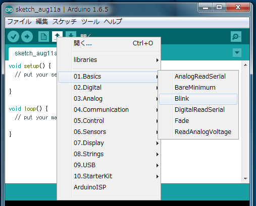
(5)[↑]開くボタンを押し、「01.Basics」_「Blink」を選択します。

(6)以下のスケッチ(プログラム)が設定されます。
/*
  Blink
  Turns on an LED on for one second, then off for one second, repeatedly.

  Most Arduinos have an on-board LED you can control. On the Uno and
  Leonardo, it is attached to digital pin 13. If you're unsure what
  pin the on-board LED is connected to on your Arduino model, check
  the documentation at http://www.arduino.cc

  This example code is in the public domain.

  modified 8 May 2014
  by Scott Fitzgerald
 */


// the setup function runs once when you press reset or power the board
void setup() {
  // initialize digital pin 13 as an output.
  pinMode(13, OUTPUT);
}

// the loop function runs over and over again forever
void loop() {
  digitalWrite(13, HIGH);   // turn the LED on (HIGH is the voltage level)
  delay(1000);              // wait for a second
  digitalWrite(13, LOW);    // turn the LED off by making the voltage LOW
  delay(1000);              // wait for a second
}
(7)[チェックマーク]検証ボタンを押すとコンパイルが実行されます。
(8)正常にコンパイルできると「コンパイル終了。」が表示されます。
(9)[→]マイコンボードに書き込むボタンを押すとプログラムが記録され実行されます。
(10)書込みが正常に完了すると「マイコンボードへの書込みが完了しました。」が表示されます。
(11)書き込まれたプログラムはすぐに実行され、サインスマート UNO R3 ATmega328P 互換ボードのLED(L)オレンジが1秒毎に点滅します。
(12)LEDのプラス側をDIGITAL-13ピン、LEDのマイナス側をGNDピンに接続すると接続したLEDも1秒毎に点滅します。(このような接続をするとLEDに大電流が流れて破損する危険があるのですが、Arduinoは電流が制限されているようです。)

(1)Arduino(アルドゥイーノ) uno組立済み基板は手ごろな価格で入手可能です。
(2)プログラムライターを使用することなく、プログラムの書込みが可能です。
(3)開発環境は「https://www.arduino.cc/en/Main/Software」からダウンロードできます。
(4)開発環境の設定はarduino-1.6.5-r2-windows.exeをダブルクリックすると全ての設定が完了しました。(USBドライバーも自動認識されました。)
(5)メニューの「ツール」_「ポート:"COM10(Arduino Uno)」_「COM10(Arduino Uno)」にチェックがはいっていることを確認します。(COM1にチェックがはいっていると正常に動作しません。、適正なポートはパソコンにより異なります。)
(6)[↑]開くボタンを押すとたくさんのサンプルプログラムを参照できる。
(7)プログラムをスケッチと呼んでいるが、シンプルでわかりやすい。
*要約するとマイコンボードは手ごろな価格で入手でき、プログラムライターは不要、開発環境はarduino-1.6.5-r2-windows.exeをダブルクリックだけで完了、たくさんのサンプルプログラムを参照でき、プログラムコードはシンプルでわかりやすい。