 Arduino(傾儖僪僁僀乕僲)墘廗嶲徠傾僪儗僗
丂Arduino(傾儖僪僁僀乕僲)墘廗偼壓婰偺傾僪儗僗傪嶲徠偟傑偡丅
https://www.arduino.cc/en/Tutorial/HomePage
Communication/MIDI偺夞楬恾丂僷僜僐儞偲偺USB愙懕偺傒偲側傝傑偡丅
丂僺儞1乮TX)傪僆僔儘偱娤嶡偟傑偡丅
Communication/MIDI偺僗働僢僠乮侾乯儊僯儏乕偺乽僼傽僀儖乿丵乽僗働僢僠偺椺乿丵乽Communication乿丵乽MIDI乿偱埲壓偺僗働僢僠偑愝掕偝傟傑偡丅
/*
 MIDI note player

 This sketch shows how to use the serial transmit pin (pin 1) to send MIDI note data.
 If this circuit is connected to a MIDI synth, it will play
 the notes F#-0 (0x1E) to F#-5 (0x5A) in sequence.

 The circuit:
 * digital in 1 connected to MIDI jack pin 5
 * MIDI jack pin 2 connected to ground
 * MIDI jack pin 4 connected to +5V through 220-ohm resistor
 Attach a MIDI cable to the jack, then to a MIDI synth, and play music.

 created 13 Jun 2006
 modified 13 Aug 2012
 by Tom Igoe
 This example code is in the public domain.
 http://www.arduino.cc/en/Tutorial/Midi
 */

void setup() {
  //  Set MIDI baud rate:
  Serial.begin(31250);
}

void loop() {
  // play notes from F#-0 (0x1E) to F#-5 (0x5A):
  for (int note = 0x1E; note < 0x5A; note ++) {
    //Note on channel 1 (0x90), some note value (note), middle velocity (0x45):
    noteOn(0x90, note, 0x45);
    delay(100);
    //Note on channel 1 (0x90), some note value (note), silent velocity (0x00):
    noteOn(0x90, note, 0x00);
    delay(100);
  }
}

//  plays a MIDI note.  Doesn't check to see that
//  cmd is greater than 127, or that data values are  less than 127:
void noteOn(int cmd, int pitch, int velocity) {
  Serial.write(cmd);
  Serial.write(pitch);
  Serial.write(velocity);
}
Communication/MIDI偺幚峴乮侾乯儊僯儏乕偺乽僗働僢僠乿丵乽儅僀僐儞儃乕僪偵彂偒崬傓乿偱彂崬傒偝傟丄幚峴偝傟傑偡丅
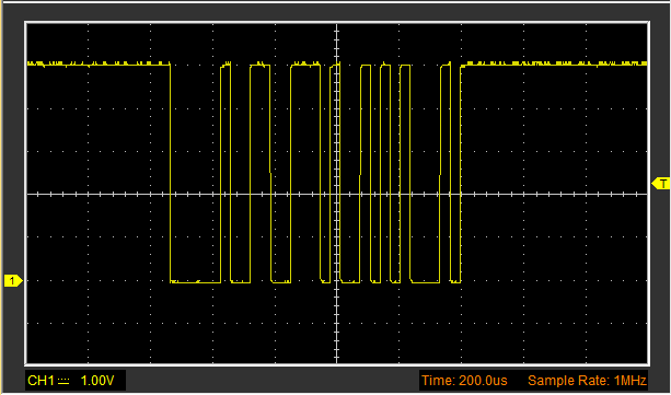
乮俀乯僺儞1乮TX)偺noteOn(0x90, note, 0x45)偵懳墳偡傞攇宍偼埲壓偲側傝傑偡丅
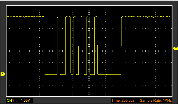
乮俁乯僺儞1乮TX)偺noteOn(0x90, note, 0x00)偵懳墳偡傞攇宍偼埲壓偲側傝傑偡丅
 Communication/MIDIl傑偲傔
乮侾乯MIDI偺儃乕儗僀僩偼31250偱屌掕偱偡丅
乮俀乯0倶90偼0僠儍儞僱儖偺壒傪弌偡僐乕僪
乮俁乯note偼廃攇悢
乮係乯0倶45偼壒偺戝偒偝
乮俆乯杮椺偱偼俁僶僀僩偺僔儕傾儖僨乕僞偑孞傝曉偟憲怣偝傟偰偄傞偙偲偑妋擣偱偒傑偡丅
乮俇乯攇宍妋擣偐傜丄惓榑棟偱偁傞偙偲偑傢偐傝傑偡丅
乮俈乯RS-232C偼晧榑棟偱亇15V偱偡偺偱曄姺偑昁梫偱偡丅
 侾俈復丗Arduino(傾儖僪僁僀乕僲)墘廗乮Control/IfStatementConditional曇乯偵峴偔丅