 Arduino(傾儖僪僁僀乕僲)墘廗嶲徠傾僪儗僗
丂Arduino(傾儖僪僁僀乕僲)墘廗偼壓婰偺傾僪儗僗傪嶲徠偟傑偡丅
https://www.arduino.cc/en/Tutorial/HomePage
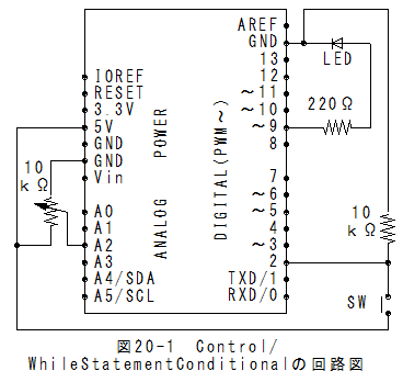
Control/WhileStatementConditional偺夞楬恾丂Control/WhileStatementConditional偺夞楬恾偼埲壓偲側傝傑偡丅
丂傾僫儘僌擖椡偑A2偲側偭偰偄傑偡偺偱拲堄偑昁梫偱偡丅
 Control/WhileStatementConditional偺僗働僢僠
乮侾乯儊僯儏乕偺乽僼傽僀儖乿丵乽僗働僢僠偺椺乿丵乽Control乿丵乽WhileStatementConditional乿 偱埲壓偺僗働僢僠偑愝掕偝傟傑偡丅
/*
  Conditionals - while statement

 This example demonstrates the use of  while() statements.
 While the pushbutton is pressed, the sketch runs the calibration routine.
 The  sensor readings during the while loop define the minimum and maximum
 of expected values from the photo resistor.

 This is a variation on the calibrate example.
 The circuit:
 * photo resistor connected from +5V to analog in pin 0
 * 10K resistor connected from ground to analog in pin 0
 * LED connected from digital pin 9 to ground through 220 ohm resistor
 * pushbutton attached from pin 2 to +5V
 * 10K resistor attached from pin 2 to ground

 created 17 Jan 2009
 modified 30 Aug 2011
 by Tom Igoe
 This example code is in the public domain.
 http://www.arduino.cc/en/Tutorial/WhileLoop
 */

// These constants won't change:
const int sensorPin = A2;       // pin that the sensor is attached to
const int ledPin = 9;           // pin that the LED is attached to
const int indicatorLedPin = 13; // pin that the built-in LED is attached to
const int buttonPin = 2;        // pin that the button is attached to


// These variables will change:
int sensorMin = 1023;  // minimum sensor value
int sensorMax = 0;     // maximum sensor value
int sensorValue = 0;         // the sensor value


void setup() {
  // set the LED pins as outputs and the switch pin as input:
  pinMode(indicatorLedPin, OUTPUT);
  pinMode (ledPin, OUTPUT);
  pinMode (buttonPin, INPUT);
}

void loop() {
  // while the button is pressed, take calibration readings:
  while (digitalRead(buttonPin) == HIGH) {
    calibrate();
  }
  // signal the end of the calibration period
  digitalWrite(indicatorLedPin, LOW);

  // read the sensor:
  sensorValue = analogRead(sensorPin);

  // apply the calibration to the sensor reading
  sensorValue = map(sensorValue, sensorMin, sensorMax, 0, 255);

  // in case the sensor value is outside the range seen during calibration
  sensorValue = constrain(sensorValue, 0, 255);

  // fade the LED using the calibrated value:
  analogWrite(ledPin, sensorValue);
}

void calibrate() {
  // turn on the indicator LED to indicate that calibration is happening:
  digitalWrite(indicatorLedPin, HIGH);
  // read the sensor:
  sensorValue = analogRead(sensorPin);

  // record the maximum sensor value
  if (sensorValue > sensorMax) {
    sensorMax = sensorValue;
  }

  // record the minimum sensor value
  if (sensorValue < sensorMin) {
    sensorMin = sensorValue;
  }
}
Control/WhileStatementConditional偺幚峴乮侾乯儊僯儏乕偺乽僗働僢僠乿丵乽儅僀僐儞儃乕僪偵彂偒崬傓乿偱彂崬傒偝傟丄幚峴偝傟傑偡丅
乮俀乯僗僀僢僠傪墴偟偰丄儃儕儏僂儉傪夞偡偲嵟戝抣偲嵟彫抣偑帺摦峑惓偝傟傑偡丅
乮俁乯僗僀僢僠傪棧偟偰丄儃儕儏僂儉傪夞偡偲LED偺柧傞偝偑曄壔偟傑偡丅
Control/WhileStatementConditional傑偲傔乮侾乯While暥偺墘廗偱偡丅
乮俀乯傾僫儘僌擖椡偑A2偲側偭偰偄傑偡偺偱拲堄偑昁梫偱偡丅
 俀侾復丗Arduino(傾儖僪僁僀乕僲)墘廗乮Control/SwitchCase曇乯偵峴偔丅