 Arduino(アルドゥイーノ)演習参照アドレス
Arduino(アルドゥイーノ)演習は下記のアドレスを参照します。
https://www.arduino.cc/en/Tutorial/HomePage
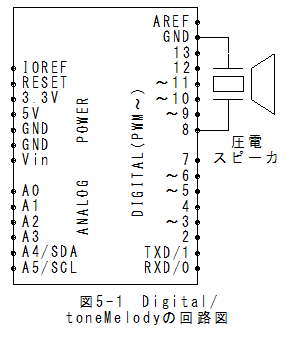
Digital/toneMelodyの回路図Digital/toneMelodyの回路図を以下に示します。
 Digital/toneMelodyのスケッチ
(1)メニューの「ファイル」_「スケッチの例」_「Digital」_「toneMelody」で以下のスケッチが設定されます。
/*
  Melody
 Plays a melody
 circuit:
 * 8-ohm speaker on digital pin 8
 created 21 Jan 2010
 modified 30 Aug 2011
 by Tom Igoe

This example code is in the public domain.
 http://www.arduino.cc/en/Tutorial/Tone
 */
#include "pitches.h"//**注(1)音階周波数定義ファイル
// notes in the melody:
int melody[] = {
  NOTE_C4, NOTE_G3, NOTE_G3, NOTE_A3, NOTE_G3, 0, NOTE_B3, NOTE_C4
};
// note durations: 4 = quarter note, 8 = eighth note, etc.:
int noteDurations[] = {
  4, 8, 8, 4, 4, 4, 4, 4
};

void setup() {
  // iterate over the notes of the melody:
  for (int thisNote = 0; thisNote < 8; thisNote++) {

    // to calculate the note duration, take one second
    // divided by the note type.
    //e.g. quarter note = 1000 / 4, eighth note = 1000/8, etc.
    int noteDuration = 1000 / noteDurations[thisNote];
    tone(8, melody[thisNote], noteDuration);

    // to distinguish the notes, set a minimum time between them.
    // the note's duration + 30% seems to work well:
    int pauseBetweenNotes = noteDuration * 1.30;
    delay(pauseBetweenNotes);
    // stop the tone playing:
    noTone(8);
  }
}

void loop() {
  // no need to repeat the melody.
}
Digital/toneMelodyの実行(1)メニューの「スケッチ」_「マイコンボードに書き込む」で書込みされ、実行されます。
(2)マイコンボードのリセットボタンを押すとメロディーが聞こえます。
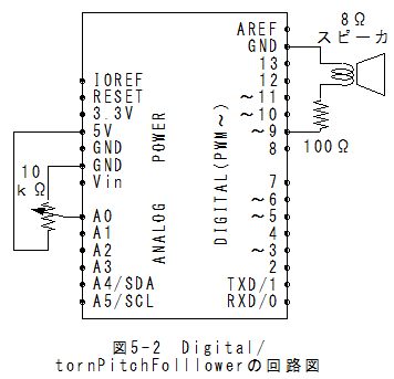
Digital/tonePitchFollowerの回路図Digital/tonePitchFollowerの回路図を以下に示します。
アナログ入力は10kΩ可変抵抗にしました。
 Digital/tonePitchFollowerのスケッチ
(1)メニューの「ファイル」_「スケッチの例」_Digital」_「tonePitchFollower」でスケッチが設定されます。
/*
  Pitch follower
 Plays a pitch that changes based on a changing analog input
 circuit:
 * 8-ohm speaker on digital pin 9
 * photoresistor on analog 0 to 5V
 * 4.7K resistor on analog 0 to ground
 created 21 Jan 2010
 modified 31 May 2012
 by Tom Igoe, with suggestion from Michael Flynn
This example code is in the public domain.
 http://www.arduino.cc/en/Tutorial/Tone2
 */
void setup() {
  // initialize serial communications (for debugging only):
  Serial.begin(9600);
}

void loop() {
  // read the sensor:
  int sensorReading = analogRead(A0);
  // print the sensor reading so you know its range
  Serial.println(sensorReading);
  // map the analog input range (in this case, 400 - 1000 from the photoresistor)
  // to the output pitch range (120 - 1500Hz)
  // change the minimum and maximum input numbers below
  // depending on the range your sensor's giving:
  int thisPitch = map(sensorReading, 400, 1000, 120, 1500);

  // play the pitch:
  tone(9, thisPitch, 10);
  delay(1);        // delay in between reads for stability
}
Digital/toneMelodyの実行(1)メニューの「スケッチ」_「マイコンボードに書き込む」で書込みされ、実行されます。
(2)メニューの「ツール」_「シリアルモニタ」を選択するとシリアルモニタが表示されます。
(3)ボリュウムを回すとsensorReading値が0から1023の範囲で変化することが確認できます。
(4)sensorReading値に応じて、音程が変化します。
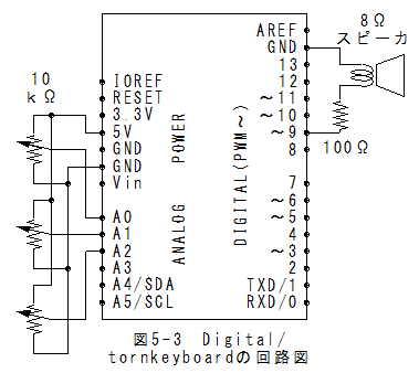
Digital/tornkeyboardの回路図Digital/tornkeyboardの回路図を以下に示します。
アナログ入力は10kΩ可変抵抗にしました。
 Digital/tornkeyboardのスケッチ
(1)(1)メニューの「ファイル」_「スケッチの例」_Digital」_「tornkeyboard」でスケッチが設定されます。
/*
  keyboard
 Plays a pitch that changes based on a changing analog input
 circuit:
 * 3 force-sensing resistors from +5V to analog in 0 through 5
 * 3 10K resistors from analog in 0 through 5 to ground
 * 8-ohm speaker on digital pin 8
 created 21 Jan 2010
 modified 9 Apr 2012
 by Tom Igoe
This example code is in the public domain.
 http://www.arduino.cc/en/Tutorial/Tone3
 */

#include "pitches.h"
const int threshold = 10;    // minimum reading of the sensors that generates a note
// notes to play, corresponding to the 3 sensors:
int notes[] = {
  NOTE_C2, NOTE_C3, NOTE_C4
};

void setup() {

}

void loop() {
  for (int thisSensor = 0; thisSensor < 3; thisSensor++) {
    // get a sensor reading:
    int sensorReading = analogRead(thisSensor);

    // if the sensor is pressed hard enough:
    if (sensorReading > threshold) {
      // play the note corresponding to this sensor:
      tone(8, notes[thisSensor], 20);
    }
  }
}
Digital/tornkeyboardの実行(1)メニューの「スケッチ」_「マイコンボードに書き込む」で書込みされ、実行されます。
(2)最初はA0、A1、A2電圧は小さく設定します。
(3)ボリュウムを回して電圧を上げると対応した音程がスピーカから聞こえます。
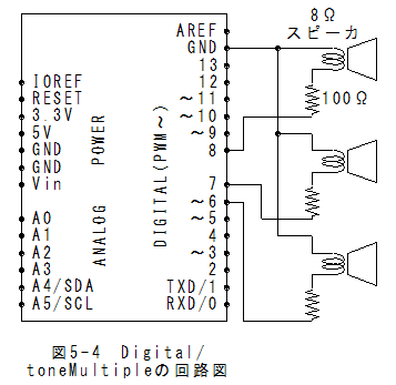
Digital/toneMultipleの回路図Digital/toneMultipleの回路図を以下に示します。
 Digital/toneMultipleのスケッチ
(1)メニューの「ファイル」_「スケッチの例」_「Digital」_「toneMultiple」で以下のスケッチが設定されます。
/*
  Multiple tone player
 Plays multiple tones on multiple pins in sequence
 circuit:
 * 3 8-ohm speaker on digital pins 6, 7, and 8
 created 8 March 2010
 by Tom Igoe
 based on a snippet from Greg Borenstein
This example code is in the public domain.
 http://www.arduino.cc/en/Tutorial/Tone4
 */

void setup() {
}

void loop() {
  // turn off tone function for pin 8:
  noTone(8);
  // play a note on pin 6 for 200 ms:
  tone(6, 440, 200);
  delay(200);

  // turn off tone function for pin 6:
  noTone(6);
  // play a note on pin 7 for 500 ms:
  tone(7, 494, 500);
  delay(500);

  // turn off tone function for pin 7:
  noTone(7);
  // play a note on pin 8 for 500 ms:
  tone(8, 523, 300);
  delay(300);
}
Digital/toneMultipleの実行(1)メニューの「スケッチ」_「マイコンボードに書き込む」で書込みされ、実行されます。
(2)3個のスピーカからそれぞれ音がします。
Arduino(アルドゥイーノ)演習(Digital-02編)まとめ(1)Digital/toneMelodyではtone(8, melody[thisNote], noteDuration)関数の使用方法が理解できます。
(2)Digital/tonePitchFollowerでは、map(sensorReading, 400, 1000, 120, 1500)関数の使用方法が理解できます。
(3)スピーカは圧電スピーカと8Ωスピーカの接続が可能であることが理解できます。
*tone(ピン番号、周波数、時間ms)とmap(変数、変換前下限、変換前上限、変換後下限、変換後上限)がポイント!!
 6章:Arduino(アルドゥイーノ)演習(Analog編)に行く。