 Arduino(アルドゥイーノ)演習参照アドレス
Arduino(アルドゥイーノ)演習は下記のアドレスを参照します。
https://www.arduino.cc/en/Tutorial/HomePage
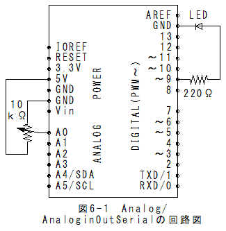
Analog/AnaloginOutSerialの回路図Analog/AnaloginOutSerialの回路図を以下に示します。
 Analog/AnaloginOutSerialのスケッチ
(1)メニューの「ファイル」_「スケッチの例」_「Analog」_「AnaloginOutSerial」で以下のスケッチが設定されます。
/*
  Analog input, analog output, serial output
 Reads an analog input pin, maps the result to a range from 0 to 255
 and uses the result to set the pulsewidth modulation (PWM) of an output pin.
 Also prints the results to the serial monitor.

 The circuit:
 * potentiometer connected to analog pin 0.
   Center pin of the potentiometer goes to the analog pin.
   side pins of the potentiometer go to +5V and ground
 * LED connected from digital pin 9 to ground

 created 29 Dec. 2008
 modified 9 Apr 2012
 by Tom Igoe
 This example code is in the public domain.
 */
// These constants won't change.  They're used to give names
// to the pins used:
const int analogInPin = A0;  // Analog input pin that the potentiometer is attached to
const int analogOutPin = 9; // Analog output pin that the LED is attached to
int sensorValue = 0;        // value read from the pot
int outputValue = 0;        // value output to the PWM (analog out)

void setup() {
  // initialize serial communications at 9600 bps:
  Serial.begin(9600);
}

void loop() {
  // read the analog in value:
  sensorValue = analogRead(analogInPin);
  // map it to the range of the analog out:
  outputValue = map(sensorValue, 0, 1023, 0, 255);
  // change the analog out value:
  analogWrite(analogOutPin, outputValue);

  // print the results to the serial monitor:
  Serial.print("sensor = " );
  Serial.print(sensorValue);
  Serial.print("\t output = ");
  Serial.println(outputValue);

  // wait 2 milliseconds before the next loop
  // for the analog-to-digital converter to settle
  // after the last reading:
  delay(2);
}
Analog/AnaloginOutSerialの実行(1)メニューの「スケッチ」_「マイコンボードに書き込む」で書込みされ、実行されます。
(2)メニューの「ツール」_「シリアルモニタ」を選択するとシリアルモニタが表示されます。
(3)ボリュウムを回すとsensor値が0から1023の範囲で変化することが確認できます。
(4)連動してoutput値が0から255の範囲で変化することが確認できます。
(5)同時にLEDの明るさが変化することが確認できます。
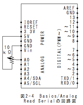
Analog/AnalogInputの回路図Analog/AnalogInputの回路図はBasics/Analog Read Serialの回路図と同じになります。
 Analog/AnalogInputのスケッチ
(1)メニューの「ファイル」_「スケッチの例」_「Analog」_「AnalogInput」で以下のスケッチが設定されます。
/*
  Analog Input
 Demonstrates analog input by reading an analog sensor on analog pin 0 and
 turning on and off a light emitting diode(LED)  connected to digital pin 13.
 The amount of time the LED will be on and off depends on
 the value obtained by analogRead().
 The circuit:
 * Potentiometer attached to analog input 0
 * center pin of the potentiometer to the analog pin
 * one side pin (either one) to ground
 * the other side pin to +5V
 * LED anode (long leg) attached to digital output 13
 * LED cathode (short leg) attached to ground

 * Note: because most Arduinos have a built-in LED attached
 to pin 13 on the board, the LED is optional.
 Created by David Cuartielles
 modified 30 Aug 2011
 By Tom Igoe
 This example code is in the public domain.
 http://www.arduino.cc/en/Tutorial/AnalogInput
 */

int sensorPin = A0;    // select the input pin for the potentiometer
int ledPin = 13;      // select the pin for the LED
int sensorValue = 0;  // variable to store the value coming from the sensor

void setup() {
  // declare the ledPin as an OUTPUT:
  pinMode(ledPin, OUTPUT);
}

void loop() {
  // read the value from the sensor:
  sensorValue = analogRead(sensorPin);
  // turn the ledPin on
  digitalWrite(ledPin, HIGH);
  // stop the program for  milliseconds:
  delay(sensorValue);
  // turn the ledPin off:
  digitalWrite(ledPin, LOW);
  // stop the program for for  milliseconds:
  delay(sensorValue);
}
Analog/AnalogInputの実行(1)メニューの「スケッチ」_「マイコンボードに書き込む」で書込みされ、実行されます。
(2)ボリュウムを回すとLED(L)オレンジの点滅速度げ変化します。
Analog/Calibrationの回路図Analog/Calibrationの回路図はAnalog/AnaloginOutSerialの回路図と同じになります。。
Analog/Calibrationのスケッチ(1)メニューの「ファイル」_「スケッチの例」_「Analog」_「Calibration」でスケッチが設定されます。
/*
  Calibration
 Demonstrates one technique for calibrating sensor input.  The
 sensor readings during the first five seconds of the sketch
 execution define the minimum and maximum of expected values
 attached to the sensor pin.

 The sensor minimum and maximum initial values may seem backwards.
 Initially, you set the minimum high and listen for anything
 lower, saving it as the new minimum. Likewise, you set the
 maximum low and listen for anything higher as the new maximum.

 The circuit:
 * Analog sensor (potentiometer will do) attached to analog input 0
 * LED attached from digital pin 9 to ground
 created 29 Oct 2008
 By David A Mellis
 modified 30 Aug 2011
 By Tom Igoe
 http://www.arduino.cc/en/Tutorial/Calibration
 This example code is in the public domain.
 */

// These constants won't change:
const int sensorPin = A0;    // pin that the sensor is attached to
const int ledPin = 9;        // pin that the LED is attached to

// variables:
int sensorValue = 0;         // the sensor value
int sensorMin = 1023;        // minimum sensor value
int sensorMax = 0;           // maximum sensor value

void setup() {
  // turn on LED to signal the start of the calibration period:
  pinMode(13, OUTPUT);
  digitalWrite(13, HIGH);

  // calibrate during the first five seconds
  while (millis() < 5000) {
    sensorValue = analogRead(sensorPin);

    // record the maximum sensor value
    if (sensorValue > sensorMax) {
      sensorMax = sensorValue;
    }

    // record the minimum sensor value
    if (sensorValue < sensorMin) {
      sensorMin = sensorValue;
    }
  }

  // signal the end of the calibration period
  digitalWrite(13, LOW);
}

void loop() {
  // read the sensor:
  sensorValue = analogRead(sensorPin);

  // apply the calibration to the sensor reading
  sensorValue = map(sensorValue, sensorMin, sensorMax, 0, 255);

  // in case the sensor value is outside the range seen during calibration
  sensorValue = constrain(sensorValue, 0, 255);

  // fade the LED using the calibrated value:
  analogWrite(ledPin, sensorValue);
}
Analog/Calibrationの実行(1)メニューの「スケッチ」_「マイコンボードに書き込む」で書込みされ、実行されます。
(2)リセットボタンを押した後、5秒以内にボリュウムを回して最小値と最大値を設定します。
(3)ボリュウムを回すとLEDの明るさが変化します。
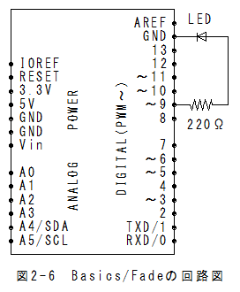
Analog/Fadingの回路図Analog/Fadingの回路図はBasics/Fadeの回路図と同じになります。
 Analog/Fadingのスケッチ
(1)メニューの「ファイル」_「スケッチの例」_「Analog」_「Fading」でスケッチが設定されます。
/*
 Fading
 This example shows how to fade an LED using the analogWrite() function.
 The circuit:
 * LED attached from digital pin 9 to ground.
 Created 1 Nov 2008
 By David A. Mellis
 modified 30 Aug 2011
 By Tom Igoe
 http://www.arduino.cc/en/Tutorial/Fading
 This example code is in the public domain.
 */

int ledPin = 9;    // LED connected to digital pin 9

void setup() {
  // nothing happens in setup
}

void loop() {
  // fade in from min to max in increments of 5 points:
  for (int fadeValue = 0 ; fadeValue <= 255; fadeValue += 5) {
    // sets the value (range from 0 to 255):
    analogWrite(ledPin, fadeValue);
    // wait for 30 milliseconds to see the dimming effect
    delay(30);
  }

  // fade out from max to min in increments of 5 points:
  for (int fadeValue = 255 ; fadeValue >= 0; fadeValue -= 5) {
    // sets the value (range from 0 to 255):
    analogWrite(ledPin, fadeValue);
    // wait for 30 milliseconds to see the dimming effect
    delay(30);
  }
}
Analog/Fadingの実行(1)メニューの「スケッチ」_「マイコンボードに書き込む」で書込みされ、実行されます。
(2)LEDの明るさが変化します。
Analog/Smoothingの回路図Analog/Smoothingの回路図はBasics/Analog Read Serialの回路図と同じになります
Analog/Smoothingのスケッチ(1)メニューの「ファイル」_「スケッチの例」_「Analog」_「Smoothing」でスケッチが設定されます。
/*
  Smoothing
  Reads repeatedly from an analog input, calculating a running average
  and printing it to the computer.  Keeps ten readings in an array and
  continually averages them.
  The circuit:
    * Analog sensor (potentiometer will do) attached to analog input 0
  Created 22 April 2007
  By David A. Mellis
  modified 9 Apr 2012
  by Tom Igoe
  http://www.arduino.cc/en/Tutorial/Smoothing
  This example code is in the public domain.
*/
// Define the number of samples to keep track of.  The higher the number,
// the more the readings will be smoothed, but the slower the output will
// respond to the input.  Using a constant rather than a normal variable lets
// use this value to determine the size of the readings array.
const int numReadings = 10;

int readings[numReadings];      // the readings from the analog input
int readIndex = 0;              // the index of the current reading
int total = 0;                  // the running total
int average = 0;                // the average
int inputPin = A0;

void setup()
{
  // initialize serial communication with computer:
  Serial.begin(9600);
  // initialize all the readings to 0:
  for (int thisReading = 0; thisReading < numReadings; thisReading++)
    readings[thisReading] = 0;
}

void loop() {
  // subtract the last reading:
  total = total - readings[readIndex];
  // read from the sensor:
  readings[readIndex] = analogRead(inputPin);
  // add the reading to the total:
  total = total + readings[readIndex];
  // advance to the next position in the array:
  readIndex = readIndex + 1;

  // if we're at the end of the array...
  if (readIndex >= numReadings)
    // ...wrap around to the beginning:
    readIndex = 0;

  // calculate the average:
  average = total / numReadings;
  // send it to the computer as ASCII digits
  Serial.println(average);
  delay(1);        // delay in between reads for stability
}
Analog/Smoothingの実行(1)メニューの「スケッチ」_「マイコンボードに書き込む」で書込みされ、実行されます。
(2)メニューの「ツール」_「シリアルモニタ」を選択するとシリアルモニタが表示されます。
(3)10個の移動平均値が表示されます。
Arduino(アルドゥイーノ)演習(Analog編)まとめ(1)Analog/AnaloginOutSerialでanalogRead(analogInPin)関数、map(sensorValue, 0, 1023, 0, 255)関数、 analogWrite(analogOutPin, outputValue)関数の使い方が理解できます。
(2)Analog/AnalogInputはアナログ入力による点滅時間制御例です。
(3)Analog/Calibrationは最初の5秒間で最小値と最大値を決定します。
(4)Analog/FadingはLEDの明るさ制御例です。
(5)Analog/Smoothingはアナログ入力の移動平均処理を行います。
 7章:Arduino(アルドゥイーノ)演習(Communication-01編)に行く。