 Arduino演習Communication/SerialCallResponseASCII用スケッチ
Arduino演習Communication/SerialCallResponseASCII用スケッチは以下となります。
//SerialCallResponseASCII
// This example code is in the public domain.

import processing.serial.*;     // import the Processing serial library
Serial myPort;                  // The serial port

float bgcolor;			// Background color
float fgcolor;			// Fill color
float xpos, ypos;	        // Starting position of the ball

void setup() {
  size(640,480);

  // List all the available serial ports
 // if using Processing 2.1 or later, use Serial.printArray()
  println(Serial.list());

  // I know that the first port in the serial list on my mac
  // is always my  Arduino module, so I open Serial.list()[0].
  // Change the 0 to the appropriate number of the serial port
  // that your microcontroller is attached to.
  myPort = new Serial(this, Serial.list()[4], 9600);

  // read bytes into a buffer until you get a linefeed (ASCII 10):
  myPort.bufferUntil('\n');

  // draw with smooth edges:
  smooth();
}

void draw() {
  background(bgcolor);
  fill(fgcolor);
  // Draw the shape
  ellipse(xpos, ypos, 20, 20);
}

// serialEvent  method is run automatically by the Processing applet
// whenever the buffer reaches the  byte value set in the bufferUntil()
// method in the setup():

void serialEvent(Serial myPort) {
  // read the serial buffer:
  String myString = myPort.readStringUntil('\n');
  // if you got any bytes other than the linefeed:
    myString = trim(myString);

    // split the string at the commas
    // and convert the sections into integers:
    int sensors[] = int(split(myString, ','));

    // print out the values you got:
    for (int sensorNum = 0; sensorNum < sensors.length; sensorNum++) {
      print("Sensor " + sensorNum + ": " + sensors[sensorNum] + "\t");
    }
    // add a linefeed after all the sensor values are printed:
    println();
    if (sensors.length > 1) {
      xpos = map(sensors[0], 0,1023,0,width);
      ypos = map(sensors[1], 0,1023,0,height);
      fgcolor = sensors[2];
    }
    // send a byte to ask for more data:
    myPort.write("A");
  }
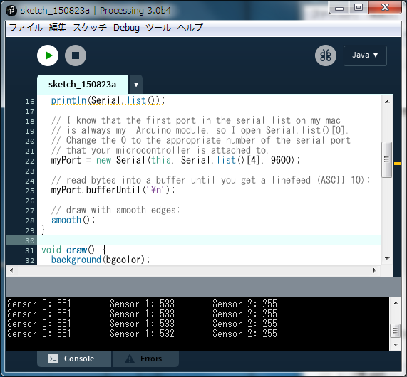
Arduino演習Communication/SerialCallResponseASCII用スケッチの実行(1)PArduino演習Communication/SerialCallResponseASCII用スケッチを実行するとコンソールに
COM1 COM3 COM4 COM5 COM10
と表示されます。
(2)Arduinoと接続のポートはいつもCOM10であり、port = new Serial(this, Serial.list()[4], 9600);とするとつながります。
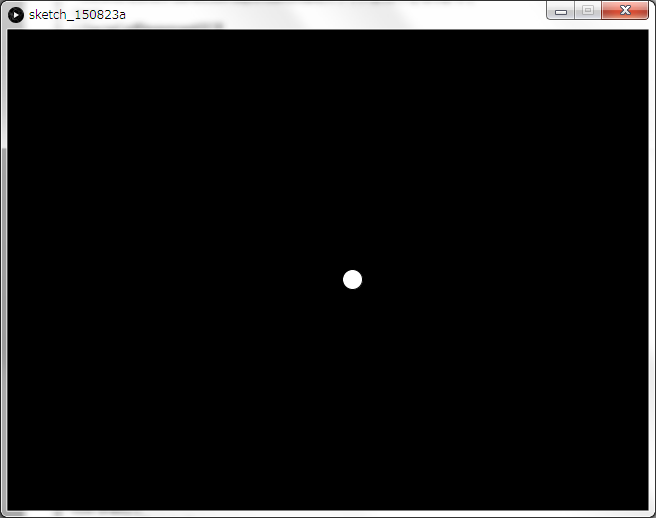
(3)コンソールには、X位置とY位置とスイッチのON/OFFが表示されます。
(4)スイッチのONのときコンソール画面は以下のようになります。
(5)スイッチがONの時の実行画面は以下のようになります。
 Arduino演習Communication/SerialCallResponseASCII用スケッチまとめ
(1)トラブルなく、動作も安定しています。
(2)起動時のみArduinoからコード"0,0,0\r\n"が送信されます。
(3)パソコン側では、"\n"までの文字列を読み込みます。
(4)パソコン側で受信可能となったら、文字”A”を送信します。
(5)Arduino側で何かの文字を受信したら、X値、Y値、ON/OFFのデータ("549,530,255\r\n")を送信します。
(6)こうすると受信処理が確実に実行できそうです。
 8章:3Dサンプル(sketch_3D_MyJet):に行く。