 ESP-WROOM-02��EEPROM 24FC256-I/P�iI2C)����̎Q�l�A�h���X
�T�O�́FArduino���K�iEEPROM 24FC256-I/P�ҁj
http://skomo.o.oo7.jp/f47/hp47_50.htm
�@Arduino UNO��ESP-WROOM-02��EEPROM 24FC256-I/P��I2C����ɂ����āA�݊���������܂��B�������AESP-WROOM-02�̃V���A�� �ʐM�̃{�|���[�g��115200bps�ɐݒ肷��K�v������܂��B
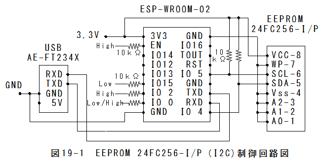
ESP-WROOM-02��EEPROM 24FC256-I/P�iI2C)�����H�}�@ESP-WROOM-02��EEPROM 24FC256-I/P�iI2C)�����H�}���ȉ��Ɏ����܂��B
 �X�P�b�`�̍쐬
�i�P�j�iSerial.begin(9600);��Serial.begin(115200);�ɕύX�ύX���܂��B**��(1)
�i�Q�j�d����������̉��s��lj����܂��B**��(2))
//EEPROM24FC256-I/P #include#define disk1 0x50 //Address of 24LC256 eeprom chip void setup(void) { Serial.begin(115200);//**��(1) Wire.begin(); unsigned int address; Serial.println("");//**��(2) for(address=0;address<10;address++) { writeEEPROM(disk1, address, 255-address); Serial.print(address, DEC); Serial.print("\t"); Serial.println(readEEPROM(disk1, address), DEC); } } void loop(){} void writeEEPROM(int deviceaddress, unsigned int eeaddress, byte data ) { Wire.beginTransmission(deviceaddress); Wire.write((int)(eeaddress >> 8)); // MSB Wire.write((int)(eeaddress & 0xFF)); // LSB Wire.write(data); Wire.endTransmission(); delay(5); } byte readEEPROM(int deviceaddress, unsigned int eeaddress ) { byte rdata = 0xFF; Wire.beginTransmission(deviceaddress); Wire.write((int)(eeaddress >> 8)); // MSB Wire.write((int)(eeaddress & 0xFF)); // LSB Wire.endTransmission(); Wire.requestFrom(deviceaddress,1); if (Wire.available()) rdata = Wire.read(); return rdata; }
�X�P�b�`�̏������i�P�jESP-WROOM-02�̃t���b�V�������������̃s���ݒ�
*EN�s���F�iChip Enable.�j��High(10k���v���A�b�v�j
*GPIO-15�s���F�iType�@I/O�@MTDO�GHSPI_CS; UART0_RTS)��LowHigh(10k���v���_�E���j
*GPIO-2�s���F�iType�@I/O�@UART Tx during flash programming)��High(10k���v���A�b�v�j
*GPIO-0�s���F�iType�@I/O�@SPI_CS2)��Low(10k���v���_�E���j�iLow���b�V�������������[�h�j
*TX�s���F�t�r�a�V���A���ϊ����W���[����RX
*RX�s���F�t�r�a�V���A���ϊ����W���[����TX
*GND�s���F�t�r�a�V���A���ϊ����W���[����GND
�i�Q�jESP-WROOM-02�̓d���𓊓����܂��B
�i�R�j���j���[�u�c�[���v�Q�u�|�[�g�v�Q�uCOM14�v��I�����܂��B
�i�S�j���j���[�u�X�P�b�`�v�Q�u�}�C�R���{�[�h�ɏ����ށv��I�����܂��B
�i�T�j�����݂��������܂��B
�i�U�jGPIO-0�s���F�iType�@I/O�@SPI_CS2)��High(10k���v���A�b�v�j�ɖ߂��܂��B
�i�V�jESP-WROOM-02�̓d�����ē������܂��B
���쎎���i�P�jarduino.exe���N�����āA�V���A�����j�^���J���܂��B
�i�Q�jGPIO-0�s���F�iType�@I/O�@SPI_CS2)��High(10k���v���A�b�v�j�ɖ߂��AESP-WROOM-02�̓d�����ē������܂��B
�i�R�j�V���A�����j�^�̎�M�f�[�^���ȉ��Ɏ����܂��B
0	255
1	254
2	253
3	252
4	251
5	250
6	249
7	248
8	247
9	246
ESP-WROOM-02��EEPROM 24FC256-I/P�iI2C)����܂Ƃ��i�P�jArduino UNO��ESP-WROOM-02��EEPROM 24FC256-I/P�iI2C)����ɂ����āA�݊���������܂��B
�i�Q�j�������AESP-WROOM-02�̃V���A���ʐM�̃{�|���[�g��115200bps�ɐݒ肷��K�v������܂��B
 �Q�O�́FESP-WROOM-02��HC-SR04 �����g�����Z���T�[�����ɍs���B