 俀侽復丗ESP-WROOM-02偱HC-SR04 挻壒攇嫍棧僙儞僒乕儌僕儏乕儖惂屼偺嶲峫傾僪儗僗
係侽復丗Arduino墘廗乮HC-SR04 挻壒攇嫍棧僙儞僒乕儌僕儏乕儖曇乯
http://skomo.o.oo7.jp/f47/hp47_40.htm
丂Arduino UNO偲ESP-WROOM-02偼HC-SR04 挻壒攇嫍棧僙儞僒乕儌僕儏乕儖惂屼偵偍偄偰丄屳姺惈偑偁傝傑偡丅偨偩偟丄ESP-WROOM-02偺僔儕傾儖 捠怣偺儃亅儗乕僩偼115200bps偵愝掕偡傞昁梫偑偁傝傑偡丅
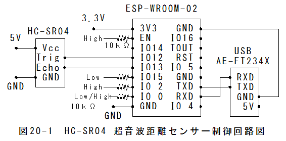
HC-SR04 挻壒攇嫍棧僙儞僒乕惂屼夞楬恾丂HC-SR04 挻壒攇嫍棧僙儞僒乕惂屼夞楬恾傪埲壓偵帵偟傑偡丅
 僗働僢僠偺嶌惉
乮侾乯const int pingPin = 12;//**7仺12偵曄峏
乮俀乯const int inPin = 13;//**8仺13曄峏
乮俁乯Serial.begin(9600);仺Serial.begin(115200);偵曄峏曄峏偟傑偡丅**拲
乮係乯delay(1000);//**100仺1000偵曄峏
/*
丂 HC-SR04
丂 Ping))) Sensor
This sketch reads a PING))) ultrasonic rangefinder and returns the
distance to the closest object in range. To do this, it sends a pulse
to the sensor to initiate a reading, then listens for a pulse
to return. The length of the returning pulse is proportional to
the distance of the object from the sensor.
The circuit:
* +V connection of the PING))) attached to +5V
* GND connection of the PING))) attached to ground
* SIG connection of the PING))) attached to digital pin 7
http://www.arduino.cc/en/Tutorial/Ping
created 3 Nov 2008
by David A. Mellis
modified 30 Aug 2011
by Tom Igoe
This example code is in the public domain.
*/
// this constant won't change. It's the pin number
// of the sensor's output:
const int pingPin = 12;//**曄峏
const int inPin = 13;//**曄峏
void setup() {
// initialize serial communication:
Serial.begin(115200);//**曄峏
}
void loop()
{
// establish variables for duration of the ping,
// and the distance result in inches and centimeters:
long duration, inches, cm;
// The PING))) is triggered by a HIGH pulse of 2 or more microseconds.
// Give a short LOW pulse beforehand to ensure a clean HIGH pulse:
pinMode(pingPin, OUTPUT);
digitalWrite(pingPin, LOW);
delayMicroseconds(2);
digitalWrite(pingPin, HIGH);
delayMicroseconds(10);
digitalWrite(pingPin, LOW);
// The same pin is used to read the signal from the PING))): a HIGH
// pulse whose duration is the time (in microseconds) from the sending
// of the ping to the reception of its echo off of an object.
pinMode(inPin,INPUT);
duration = pulseIn(inPin, HIGH);
// convert the time into a distance
inches = microsecondsToInches(duration);
cm = microsecondsToCentimeters(duration);
Serial.print(inches);
Serial.print("in, ");
Serial.print(cm);
Serial.print("cm");
Serial.println();
delay(1000);//**曄峏
}
long microsecondsToInches(long microseconds)
{
// According to Parallax's datasheet for the PING))), there are
// 73.746 microseconds per inch (i.e. sound travels at 1130 feet per
// second). This gives the distance travelled by the ping, outbound
// and return, so we divide by 2 to get the distance of the obstacle.
// See: http://www.parallax.com/dl/docs/prod/acc/28015-PING-v1.3.pdf
return microseconds / 74 / 2;
}
long microsecondsToCentimeters(long microseconds)
{
// The speed of sound is 340 m/s or 29 microseconds per centimeter.
// The ping travels out and back, so to find the distance of the
// object we take half of the distance travelled.
return microseconds / 29 / 2;
}
僗働僢僠偺彂崬傒乮侾乯ESP-WROOM-02偺僼儔僢僔儏彂偒姺偊帪偺僺儞愝掕
*EN僺儞丗乮Chip Enable.乯仺High(10k兌僾儖傾僢僾乯
*GPIO-15僺儞丗乮Type丂I/O丂MTDO丟HSPI_CS; UART0_RTS)仺LowHigh(10k兌僾儖僟僂儞乯
*GPIO-2僺儞丗乮Type丂I/O丂UART Tx during flash programming)仺High(10k兌僾儖傾僢僾乯
*GPIO-0僺儞丗乮Type丂I/O丂SPI_CS2)仺Low(10k兌僾儖僟僂儞乯乮Low偱儔僢僔儏彂偒姺偊儌乕僪乯
*TX僺儞丗倀俽俛僔儕傾儖曄姺儌僕儏乕儖偺RX
*RX僺儞丗倀俽俛僔儕傾儖曄姺儌僕儏乕儖偺TX
*GND僺儞丗倀俽俛僔儕傾儖曄姺儌僕儏乕儖偺GND
乮俀乯ESP-WROOM-02偺揹尮傪搳擖偟傑偡丅
乮俁乯儊僯儏乕乽僣乕儖乿丵乽億乕僩乿丵乽COM14乿傪慖戰偟傑偡丅
乮係乯儊僯儏乕乽僗働僢僠乿丵乽儅僀僐儞儃乕僪偵彂崬傓乿傪慖戰偟傑偡丅
乮俆乯彂崬傒偑姰椆偟傑偡丅
乮俇乯GPIO-0僺儞丗乮Type丂I/O丂SPI_CS2)仺High(10k兌僾儖傾僢僾乯偵栠偟傑偡丅
乮俈乯ESP-WROOM-02偺揹尮傪嵞搳擖偟傑偡丅
摦嶌帋尡乮侾乯arduino.exe傪婲摦偟偰丄僔儕傾儖儌僯僞傪奐偒傑偡丅
乮俀乯GPIO-0僺儞丗乮Type丂I/O丂SPI_CS2)仺High(10k兌僾儖傾僢僾乯偵栠偟丄ESP-WROOM-02偺揹尮傪嵞搳擖偟傑偡丅
乮俁乯僔儕傾儖儌僯僞偺庴怣僨乕僞傪埲壓偵帵偟傑偡丅
33in, 86cm
33in, 86cm
33in, 85cm
33in, 85cm
33in, 85cm
33in, 85cm
33in, 85cm
33in, 86cm
33in, 86cm
33in, 86cm
33in, 86cm
33in, 86cm
33in, 85cm
33in, 86cm
33in, 85cm
33in, 85cm
33in, 85cm
33in, 86cm
33in, 85cm
33in, 86cm
33in, 86cm
33in, 85cm
33in, 85cm
33in, 85cm
33in, 85cm
ESP-WROOM-02偱HC-SR04 挻壒攇嫍棧僙儞僒乕惂屼傑偲傔乮侾乯Arduino UNO偲ESP-WROOM-02偼HC-SR04 挻壒攇嫍棧僙儞僒乕惂屼偵偍偄偰丄屳姺惈偑偁傝傑偡丅
乮俀乯偨偩偟丄ESP-WROOM-02偺僔儕傾儖捠怣偺儃亅儗乕僩偼115200bps偵愝掕偡傞昁梫偑偁傝傑偡丅
 俀侾復丗ESP-WROOM-02偲Arduino UNO偺I2C捠怣屳姺惈偺専摙偵峴偔丅