processingによるWiFi無線を検討します。
 processingによるWiFi無線の参考アドレス
Network
https://processing.org/reference/libraries/net/index.html
*TCPサーバー、TCPクライアントの機能はprocessingの標準ライブラリーとして準備されています。
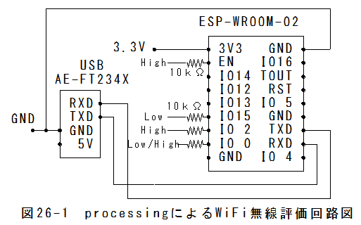
processingによるWiFi無線評価回路図processingによるWiFi無線評価回路図を以下に示します。
 processingによるWiFi無線評価回路外観
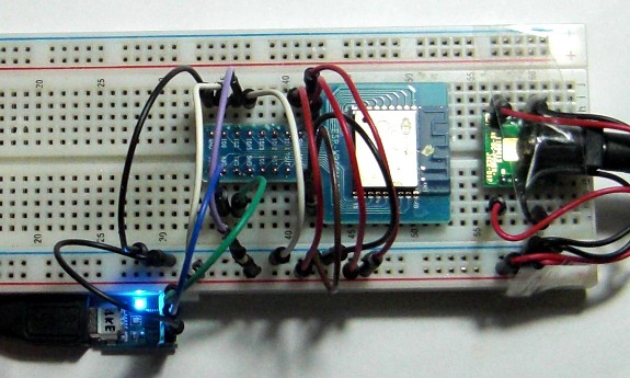
processingによるWiFi無線評価回路外観を以下に示します。
 ESP-WROOM-02用スケッチ
ESP-WROOM-02用スケッチは以下となります。
//WiFiClient 非同期
#include <ESP8266WiFi.h>
const char* ssid     = "SSID";//無線LANのSSIDを設定します。
const char* password = "password";//無線LANのpasswordを設定します。
const char* host = "192.168.11.2";//パソコンのIPアドレスを設定します。
const int httpPort = 13000;//TCPサーバのポート
static String gSendText="";

void setup() {
  Serial.begin(115200);//シリアルポートを115200bpsで開始
  delay(10);
  // We start by connecting to a WiFi network
  Serial.println();

  WiFi.begin(ssid, password);//無線LANに接続要求

  while (WiFi.status() != WL_CONNECTED) {//接続完了まで待ちます。
    delay(500);
    Serial.print(".");
  }
  Serial.println("");
  Serial.println("WiFi connected");
}

void loop()
{
  delay(500);
  // Use WiFiClient class to create TCP connections
  WiFiClient client;
  if (!client.connect(host, httpPort)) {//TCPサーバへの接続要求
    //Serial.print("x");
  }
  else
  {
    if(gSendText.length() > 1)
    {
      client.print(gSendText);//データを送信
      gSendText="";
    }
    else{client.print("a");}//"a"を送信
    delay(10);
    // Read all the lines of the reply from server and print them to Serial
    while(client.available())
    {
      String line = client.readStringUntil('\n');//受信します。
      Serial.print(line+"\r\n");
      gSendText=line + "=OK\r\n";//送信データのセット
    }
  }
}
ESP-WROOM-02用スケッチテキストファイルESP-WROOM-02用スケッチテキストファイルは以下から参照できます。
 「ESP-WROOM-02用スケッチテキストファイル」にいくスケッチの解説
(1)以下を修正します。
const char* ssid = "SSID";//無線LANのSSD
const char* password = "password";//無線LANのパスワード
const char* host = "192.168.11.2";//パソコンのIPアドレス
const int httpPort = 13000;//TCPサーバのポート
(2)Serial.begin(115200);
シリアルポートを115200bpsで開始します。
(3)WiFi.begin(ssid, password);//無線LANに接続要求
無線LANに接続を開始します。(無線LANが動作しているのが前提です。)
(4) while (WiFi.status() != WL_CONNECTED)
接続完了まで待ちます。
(5)client.connect(host, httpPort):TCPサーバへの接続要求
(6)client.print(gSendText):gSendTextにデータがセットされている場合データを送信します。
(7)client.print("a"):gSendTextにデータがセットされていない場合"a"を送信します。
(8)String line = client.readStringUntil('\n'):受信します。
上記シーケンスのポイント
*標準的なTCPサーバとクライアントの通信手順となっています。
*最初にクライアントからサーバに接続要求をします。
*接続したら、クライアントからサーバにデータを送信します。
*次にサーバからクライアントにデータを送信します。
*サーバはクライアントにデータを送信後、接続を切断し接続待ちの状態で待機します。
*サーバはほとんどの時間で接続待ちの状態で待機することになります。
*接続待ちの状態では、どのクライアントからの接続要求も受け付けるため、複数のクライアントとの通信が可能です。
Arduinoスケッチの書込み(1)制御回路図を接続します。
(2)Arduinoをダブルクリックで起動します。
(3)ESP-WROOM-02用スケッチをペーストします。
(4)GPIO-0ピン:(Type I/O SPI_CS2)→Low(10kΩプルダウン)に設定し、ESP-WROOM-02の電源を投入します。
(5)スケッチを書込みます。
processing用スケッチprocessing用スケッチは以下となります。
// Chat Server
import processing.net.*;
int port = 13000;
boolean myServerRunning = true;
int bgColor = 0;
int direction = 1;
int textLine = 60;
Server myServer;
void setup()
{
  size(200, 200);
  textFont(createFont("SanSerif", 16));
  myServer = new Server(this, port); // Starts a myServer on port 13000
  background(0);
}

void mousePressed()
{
  // If the mouse clicked the myServer stops
  myServer.stop();
  myServerRunning = false;
}

void draw()
{
  if (myServerRunning == true)
  {
    text("server", 15, 45);
    Client thisClient = myServer.available();
    if (thisClient != null) {
      if (thisClient.available() > 0) {
         thisClient.write("ABC\r\n");
        println("mesage from: " + thisClient.ip() + " : " + thisClient.readString());
      }
    }
  }
  else
  {
    text("server", 15, 45);
    text("stopped", 15, 65);
  }
}
processing用スケッチテキストファイルprocessing用スケッチテキストファイルは以下から参照できます。
「processing用スケッチテキストファイル」にいく動作試験(1)processing用スケッチをRunします。
(2)arduino.exeを起動して、シリアルモニタを開きます。
(3)シリアルモニターを開きボーレート115200bpsに設定します。
(5)GPIO-0ピン:(Type I/O SPI_CS2)→High(10kΩプルアップ)に戻し、ESP-WROOM-02の電源を再投入します
(6)以下の結果が表示されます。
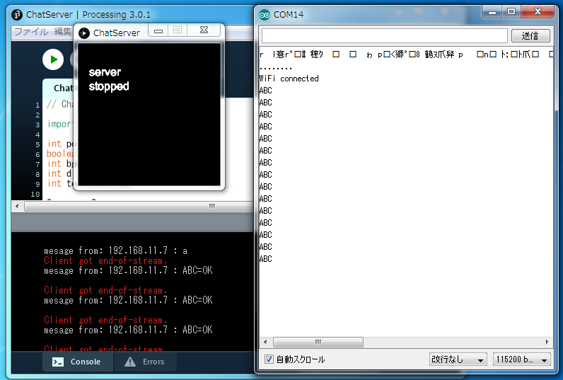 表示内容
表示内容(1)シリアルモニター
........
WiFi connected
ABC
ABC
ABC
ABC
(2)processingのコンソール
mesage from: 192.168.11.7 : a
Client got end-of-stream.
mesage from: 192.168.11.7 : ABC
=OK

Client got end-of-stream.
mesage from: 192.168.11.7 : ABC
=OK

Client got end-of-stream.
mesage from: 192.168.11.7 : ABC
=OK

Client got end-of-stream.
mesage from: 192.168.11.7 : ABC
=OK

Client got end-of-stream.
Server SocketException: socket closed
processingによるWiFi無線まとめ(1)TCPサーバー、TCPクライアントの機能はprocessingの標準ライブラリーとして準備されています。
(2)processingの標準ライブラリーを使用すると比較的簡単なスケッチでTCPサーバーを動作させることが可能であることが確認できました。
(3)ESP-WROOM-02とprocessingの組合せは、さまざまな応用の可能性がありそうです。